The 38-690XX was Philco's top of the line radio for the
1938 model year. Introduced in June of 1937 with a list
price of $395, it was the follow-on to the previous year's
premier model 37-690X. It is a 20-tube all-wave receiver
housed in an impressive cabinet that for sure embraces
the fundamental essences of machine-aged design. Re-
ferred to by Philco as Super High-Fidelity, it embodies
seven speakers and clarifiers, beam-power output, auto-
matic bass compensation, variable IF bandwidths, auto-
matic tuning, magnetic tuning, Philco's Foreign Tuning
System and five spread-band tuning ranges. All said, the
38-690XX is rightly regarded today as being one of the
finest domestic tube radios ever made.
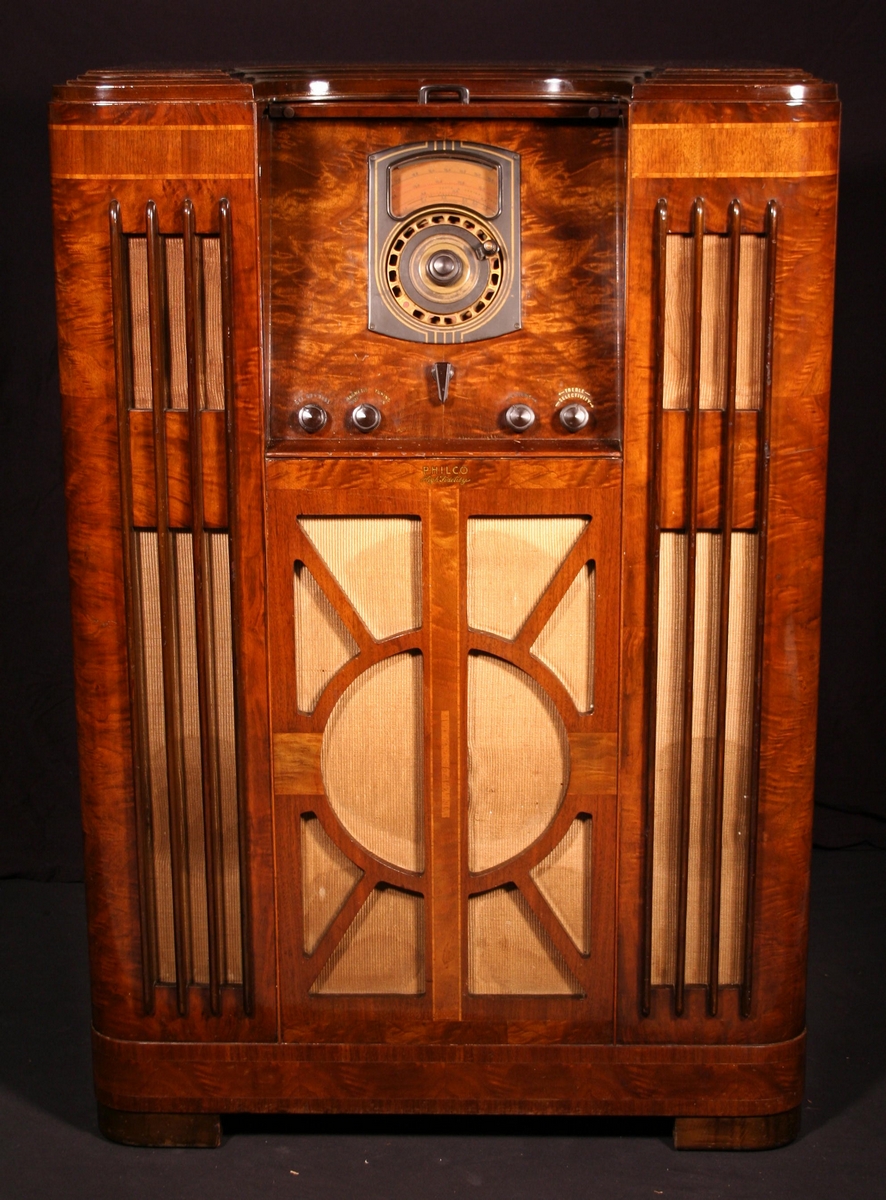
Cabinetry
Cosmetically, the 38-690XX features a fabulous cabinet
that in 1937 debuted Philco's latest contribution to their
radio art - the inclined control panel (having an angle of
approximately 30 degrees to the vertical). This was init-
ially used on eight of their 1938 models and through ex-
tensive advertising, gave rise to the popular marketing
slogan of the day: No Squat, No Stoop, No Squint. It is
of note that Philco was not the first to market such sets,
as others, such as American Bosch and Admiral, had
offered models in earlier years, though with less adver-
tising razzmatazz.
Inclined Sounding Board: By inference from its Double
X designation, the 690XX would be expected to embody
that Philco staple, the Inclined Sounding Board (ISB).
Philco used an X after the model number to signify use
of the ISB and, starting for 1938, a second X for the Inc-
lined Control Panel. However I must confess that inspect
and measure as I may, I have yet to discover the meag-
erest of inclination to the sounding board on the 690XX.
Philco advertising, when jointly overviewing 1938's 116
and 690 XX, attributes an ISB to both. However, in the
690XX details section of the ads that I've seen there is
no mention of an ISB (unlike for the 116XX - see Philco
brochure extract below right or click here). The same
appears to have been true for the 37-690X too.
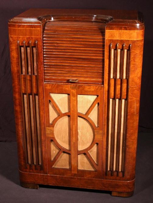
Disappearing Tambour Door: The 690XX's cabinet
dispensed with the full length doors of its predecessor,
substituting instead a Disappearing Tambour Door that
concealed the inclined control panel when rolled down
but left the loudspeaker baffle open to the room, allow-
ing the set to continue being listened to. The control
panel has the same knob layout as the 1937 model, but
features a redesigned escutcheon for the automatic-
tuning dial.
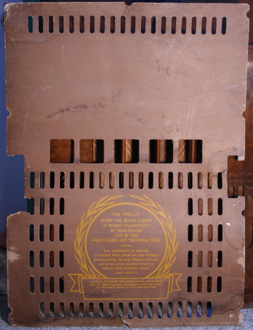
Rear Protective Screen: For 1938 many of Philco's
console models, including the 690XX, came fitted with a
protective rear screen. However this was a very flimsy
affair and is long gone from most sets today. Only the
retention clips around the rear perimeter of the cabinet
remain on mine. The screen used for the 38-116XX can
be seen here.
Technical Overview
The 5-band 38-690XX uses 20 tubes divided between a
14-tube upper tuner chassis and a 6-tube lower power-
supply and amplifier chassis. The tube line ups and tun-
ing ranges are shown lower to the right. The design was
an evolution of that of the 37-690X. The schematic may
be found here.
Audio Output: Two of the new 6L6G beam tetrodes
(introduced in June of 1936) serve for audio output in
place of the previous model's 6B4G triodes. These el-
iminated the hum problems that would occur with the
37-690X when the 6B4Gs were improperly balanced.
Bass Amplification: Several tubes serve for automatic
Bass compensation. These boost Bass output as vol-
ume diminishes, offsetting the reduced bass perception
of the human ear as the intensity level is lowered. The
circuit is similar to that used for the 37-690X, a descrip-
tion of which may be found here, courtesy of philcorep-
airbench. A continuously variable bass control knob is
provided to facilitate tailoring of the overall bass resp-
onse by the listener, forming part of what Philco called
their Musical Interpretation Control.
Loudspeaker System: This consists of a 14" primary
loudspeaker, four 8" acoustic clarifiers and a pair of 6"
high-frequency speakers. With the exception of the sub-
stitution of a 14" type W-6 cathedral speaker for the 14"
W-2, this arrangement is as discussed on my 37-690X
page.
The 6" electrodynamic high-frequency units handle much
of the high frequency output (actually, today these would
be considered no more than mid-range units). Unlike for
the 37-690X, these speakers are energized by an addit-
ional secondary winding on the driver (phase-splitter)
transformer. A series 1uF capacitor forms part of a freq-
uency selective (crossover) network, serving to isolate
the "tweeters" from too much low bass, which could dam-
age the units. See Ron Ramirez' discussion on this topic
at philcoradio.com.
Variable IF bandwidth: a fidelity control knob is used
to mechanically change the response of three of the
set's four IF transformers, as described on my 37-690X
page.
Automatic & Magnetic Tuning: For details on auto-
matic and Magnetic tuning, refer to my 37-690X page.
Foreign Tuning System: This refers to aspects of the
front-end design concerned with optimizing sensitivity of
the set and its ability to tune and separate stations from
noise. See my 37-690X page for general details.
Five Spread-Band Ranges: Band-spreading on Philco
5-band models featuring their "spread band" dial (incl-
uding the 37-116/670/675/690 and 38-116/690) is evi-
dent from the Tuning Ranges listed right, which these
sets all shared. For these models the ratio of max:min
frequency of the upper three bands is about half of what
it is on the lower bands, corresponding to wider spacing
between shortwave stations. One can compare Philco's
approach with Zenith's, which more or less standardized
on three bands (4 for the U models) each with a max:min
ratio of around 3.3. Tuning those on the crowded short-
wave bands was therefore more difficult. This was in
spite of Zenith's somewhat disingenuous advertising
claiming "tuning range of 5 wavebands on 3 simplified
dial ranges" (to be fair, Philco took liberties too, loosely
using the term spread band when describing their 1937
and 1938 three band sets). However, Philco did pay a
price for band-spreading in their 1937 5-band sets esp-
ecially, in terms of the number and complexity of tuned
circuits. For 1938, they reduced the number of 5-band
band-spread models and simplified the circuits in those
they did offer. However, as discussed in the inset below,
this was mostly not accomplished by compromising per-
formance but through a better understanding of the cir-
cuit trade-offs.
1938 model year. Introduced in June of 1937 with a list
price of $395, it was the follow-on to the previous year's
premier model 37-690X. It is a 20-tube all-wave receiver
housed in an impressive cabinet that for sure embraces
the fundamental essences of machine-aged design. Re-
ferred to by Philco as Super High-Fidelity, it embodies
seven speakers and clarifiers, beam-power output, auto-
matic bass compensation, variable IF bandwidths, auto-
matic tuning, magnetic tuning, Philco's Foreign Tuning
System and five spread-band tuning ranges. All said, the
38-690XX is rightly regarded today as being one of the
finest domestic tube radios ever made.
Cabinetry
Cosmetically, the 38-690XX features a fabulous cabinet
that in 1937 debuted Philco's latest contribution to their
radio art - the inclined control panel (having an angle of
approximately 30 degrees to the vertical). This was init-
ially used on eight of their 1938 models and through ex-
tensive advertising, gave rise to the popular marketing
slogan of the day: No Squat, No Stoop, No Squint. It is
of note that Philco was not the first to market such sets,
as others, such as American Bosch and Admiral, had
offered models in earlier years, though with less adver-
tising razzmatazz.
Inclined Sounding Board: By inference from its Double
X designation, the 690XX would be expected to embody
that Philco staple, the Inclined Sounding Board (ISB).
Philco used an X after the model number to signify use
of the ISB and, starting for 1938, a second X for the Inc-
lined Control Panel. However I must confess that inspect
and measure as I may, I have yet to discover the meag-
erest of inclination to the sounding board on the 690XX.
Philco advertising, when jointly overviewing 1938's 116
and 690 XX, attributes an ISB to both. However, in the
690XX details section of the ads that I've seen there is
no mention of an ISB (unlike for the 116XX - see Philco
brochure extract below right or click here). The same
appears to have been true for the 37-690X too.
Disappearing Tambour Door: The 690XX's cabinet
dispensed with the full length doors of its predecessor,
substituting instead a Disappearing Tambour Door that
concealed the inclined control panel when rolled down
but left the loudspeaker baffle open to the room, allow-
ing the set to continue being listened to. The control
panel has the same knob layout as the 1937 model, but
features a redesigned escutcheon for the automatic-
tuning dial.
Rear Protective Screen: For 1938 many of Philco's
console models, including the 690XX, came fitted with a
protective rear screen. However this was a very flimsy
affair and is long gone from most sets today. Only the
retention clips around the rear perimeter of the cabinet
remain on mine. The screen used for the 38-116XX can
be seen here.
Technical Overview
The 5-band 38-690XX uses 20 tubes divided between a
14-tube upper tuner chassis and a 6-tube lower power-
supply and amplifier chassis. The tube line ups and tun-
ing ranges are shown lower to the right. The design was
an evolution of that of the 37-690X. The schematic may
be found here.
Audio Output: Two of the new 6L6G beam tetrodes
(introduced in June of 1936) serve for audio output in
place of the previous model's 6B4G triodes. These el-
iminated the hum problems that would occur with the
37-690X when the 6B4Gs were improperly balanced.
Bass Amplification: Several tubes serve for automatic
Bass compensation. These boost Bass output as vol-
ume diminishes, offsetting the reduced bass perception
of the human ear as the intensity level is lowered. The
circuit is similar to that used for the 37-690X, a descrip-
tion of which may be found here, courtesy of philcorep-
airbench. A continuously variable bass control knob is
provided to facilitate tailoring of the overall bass resp-
onse by the listener, forming part of what Philco called
their Musical Interpretation Control.
Loudspeaker System: This consists of a 14" primary
loudspeaker, four 8" acoustic clarifiers and a pair of 6"
high-frequency speakers. With the exception of the sub-
stitution of a 14" type W-6 cathedral speaker for the 14"
W-2, this arrangement is as discussed on my 37-690X
page.
The 6" electrodynamic high-frequency units handle much
of the high frequency output (actually, today these would
be considered no more than mid-range units). Unlike for
the 37-690X, these speakers are energized by an addit-
ional secondary winding on the driver (phase-splitter)
transformer. A series 1uF capacitor forms part of a freq-
uency selective (crossover) network, serving to isolate
the "tweeters" from too much low bass, which could dam-
age the units. See Ron Ramirez' discussion on this topic
at philcoradio.com.
Variable IF bandwidth: a fidelity control knob is used
to mechanically change the response of three of the
set's four IF transformers, as described on my 37-690X
page.
Automatic & Magnetic Tuning: For details on auto-
matic and Magnetic tuning, refer to my 37-690X page.
Foreign Tuning System: This refers to aspects of the
front-end design concerned with optimizing sensitivity of
the set and its ability to tune and separate stations from
noise. See my 37-690X page for general details.
Five Spread-Band Ranges: Band-spreading on Philco
5-band models featuring their "spread band" dial (incl-
uding the 37-116/670/675/690 and 38-116/690) is evi-
dent from the Tuning Ranges listed right, which these
sets all shared. For these models the ratio of max:min
frequency of the upper three bands is about half of what
it is on the lower bands, corresponding to wider spacing
between shortwave stations. One can compare Philco's
approach with Zenith's, which more or less standardized
on three bands (4 for the U models) each with a max:min
ratio of around 3.3. Tuning those on the crowded short-
wave bands was therefore more difficult. This was in
spite of Zenith's somewhat disingenuous advertising
claiming "tuning range of 5 wavebands on 3 simplified
dial ranges" (to be fair, Philco took liberties too, loosely
using the term spread band when describing their 1937
and 1938 three band sets). However, Philco did pay a
price for band-spreading in their 1937 5-band sets esp-
ecially, in terms of the number and complexity of tuned
circuits. For 1938, they reduced the number of 5-band
band-spread models and simplified the circuits in those
they did offer. However, as discussed in the inset below,
this was mostly not accomplished by compromising per-
formance but through a better understanding of the cir-
cuit trade-offs.
Did the 690XX Need the Inclined Sounding Board?
Over the course of the five years since its inception
in 1932, Philco had progressively reduced the ISB's
angle of inclination (e.g. contrast the 112X and 38-
116XX). This was probably for both cosmetic and
technical reasons. In fact, with the introduction of
sound diffusing cabinets in 1934 the need for it was
somewhat diminished. On the 1937 and 1938 690
models, which used both diffusors and tweeters, it
was likely not needed at all (how many speaker
cabinets do you see using inclined baffles today?).
The original intent of the ISB was to direct medium
and high frequency sounds up towards the listener
rather than beaming them out along the floor. On
early ISB models using loudspeakers with large
cones required to handle the full frequency range
it did exactly what Philco claimed. However, tech-
nology advanced and beaming of sound became
managed, ameliorated by other, superior methods.
So was the first X in the 690 just a marketing ploy?
Probably. Philco had, through years of heavy adv-
ertising, fostered the notion that good tone quality
was in part attributable to the ISB of their X models.
So when it came to the 37-690X and 38-690XX, it
seems they were reluctant to drop the X from the
name and leave the impression that something was
amiss. Besides, had they dropped it there would
have been the quandary of where to place the sec-
ond X, for the control panel. Would they have used
38-690-X? Surely not 38-690X.
Tuning Circuit Simplifications for 1938
For its 38-690XX Philco simplified the tuned circuits
in the antenna, RF-amp and oscillator sections
compared to 1937. The number of compensators
(adjustable caps), windings and taps on coils, and
the complexities of the waveband switch were all
reduced, which would have paid off with lower man-
ufacturing cost. In all, the number of adjustable
capacitative compensators for the ANT/RF/OSC
was reduced from 26 (690X) to 10 on the 690XX!
The 38-116XX initially came in a 121 configuration
that was very similar to the 1937 model, but not
long after its introduction they simplified this too
(code 125 chassis).
Split-Stator Tuning Condensor for 1938
Of note is that for the 1938 116XX (code 125) and
690XX, each of the three gangs on the tuning cond-
ensor was formed in two sections, comprising larger
and smaller capacitative elements. On the two low-
est frequency bands the two sections of each gang
are connected in parallel through the band switch,
providing a large capacitance for tuning. On the
three highest bands only the smaller, lower capac-
ity stator is switched in.
A perusal of the Riders data for the 38-116XX's
code 125 chassis (see here - pg 9.14) reveals the
following comments: "Split Stator Tuning Conden-
sors for spreading shortwave stations further apart"
and "For bandspread purposes the stator plates of
the tuning condensor in this receiver are designed
in two sections". This invites investigation, because
it is the square root of the ratio of minimum to max-
imum capacitance (plates minimally versus maxim-
ally meshed) that is important for tuning range on
any band, not absolute capacitance; inspection of
the condensor on the 690XX suggests that this rat-
io stays constant regardless of how the stators are
configured. Besides, the 37-690X does not employ
split stators and yet has identical ranges to the 690
XX! But, to achieve this, the 37-690X required ext-
ensive padding and trimming of the condensor,
whereas the 38-116XX and 690XX get away mostly
with simplified trimming. Moreover, what the decr-
eased stator capacitance also did was require the
inductance within a tuned circuit to be increased
for a given frequency of resonance, and with this
higher inductance came benefits of higher Q and
improved tolerance to manufacturing spreads*.
The simplifications were not without impact on dial
linearity. I have created a chart (right) comparing
linearity of the 37-690X's dial with that of the 38-
690XX on Band 1 (standard broadcast) and Band
3 (made using measurements of the actual dials).
Bands 1 and, by inference 2, are very similar bet-
ween the models, which is to be expected given
that the range of the tuning condensors was likely
chosen to accommodate these with minimal pad-
ding and trimming on either set, assuming a similar
capacity versus rotation law. However for 1938 the
split stators result in a more even coverage of the
tuning range on the band-spread bands 3, 4 and
5. Band 2 is very similar to Band 1 because both
stators of each gang of the tuning condensor are
used in parallel for these bands. Likewise, bands
4 & 5 share the same characteristic as Band 3 be-
cause these all use just the smaller stators.
So it appears that use of split stators was one ena-
bling measure that allowed Philco to simplify asp-
ects of the various tuned circuits. There were prob-
ably others too. US patent #2122558 A, filed by
RCA in 1934, provides some insight into the trade-
offs faced by circuit designers and which drove
Philco to employ the split stator condensor in their
1938 5-band receivers (though RCA seems to have
overlooked this approach in their patent). For sure,
over time Philco engineers would have improved
their understanding of circuit trade-offs involved,
leading to reduced circuit complexity with not nec-
essarily compromised, but perhaps even improved
performance.
*After writing this piece, I found this excellent article
on-line that explains the use of padders and trim-
mers for bandspreading - see here and follow the
links.
| TubeRadioLand:Home > Philco > 38-690XX |
Philco 38-690XX Super 'Hi-Fi' Console Radio (1936/37)
Copyright TubeRadioLand.com
click any thumbnail to enlarge


No Longer need you "Squat, Stoop or Squint" to tune a station!

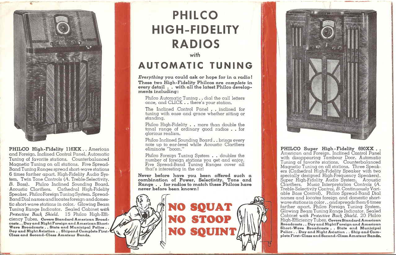
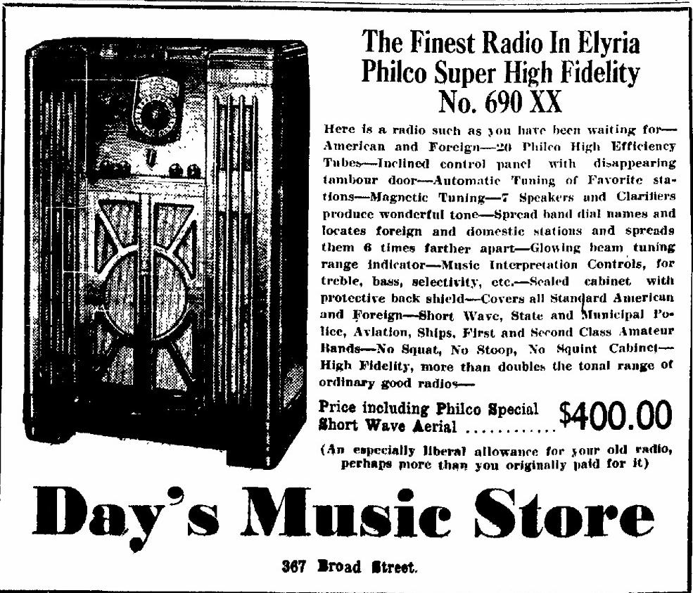

Extract from Philco 1938 Brochure (Summer 1937)
Feb 16th 1938, Ohio
RF Chassis (upper) Tube Line-Up:
6U7G RF amp
6A8G mixer
6A8G Local Oscillator
6N7G Osc control for magnetic tuning
6K7G 1st IF
6K7G 2nd IF
6J5G 2nd Detector
6B8G RF Automatic Volume Control (AVC)
6K7G Magnetic Tuning amplifier
6H6G Magnetic Tuning Discriminator
6J5G IF AVC
6R7G 1st AF
6N7G 2nd AF/Automatic Bass Amp
6K7G Automatic Bass Compensation Amp
Power Chassis (lower) Tube Line-Up:
5X4G Rectifier for first power unit
5X4G Rectifier for 2nd power unit
6J5G Bass amplifier AVC
6F6G Driver
6L6G * 2 Push-Pull audio output
Tuning ranges: max:min**
Range 1: 530 to 1600 kcs 3.02
Range 2: 1.58 to 4.75 mcs 3.01
Range 3: 4.7 to 7.4 mcs 1.57
Range 4: 7.35 to 11.6 mcs 1.58
Range 5: 11.5 to 18.2 mcs 1.58
**See Five Spread-Band Ranges to the left
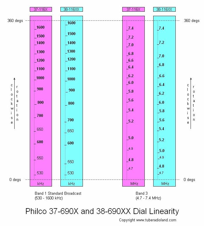
| Philco 37-690X & 38-690XX Dial Linearity (based on actual dial measurements) Note: linearity table column headers incorrectly show 116X & 116XX. These should be 690X and 690XX. |
I purchased this set in 2006. The cabinet is original but
I recently cleaned and detailed it. It is testament to the
quality of the veneers and finish on this radio that it
cleaned up so beautifully. A showpiece for sure. The
chassis is unrestored, but played upon being brought
up slowly on a variac for a short while. I plan to have it
on the bench for a full restoration this winter (2015/16)!